BattPulse
Securing the Energy Transformation
Leader Battery Management System
Product Technical Datasheet
6S–126S
Passive Balancing
CAN + WiFi
Up to 400 A
Complete technical specifications, electrical data, connector pinouts,
communication interfaces, and ordering information.
Contents
- Product Overview
- Key Features
- Electrical Specifications
- Measurement & Protection
- Communication Interfaces
- Digital Inputs & Outputs
- Connectors & Pinouts
- Mechanical & Environmental
- Daisy-Chain & High-Voltage Packs
- Ecosystem & Compatibility
- Ordering Information
- Document Revision History
1. Product Overview
The BattPulse Leader BMS is a professional-grade battery management system designed for EV conversions, energy storage systems, e–bike/e–boat builds, and industrial battery packs. It features a high-accuracy 16-bit analogue front-end for per-cell voltage monitoring, a high-precision shunt-based current sensor, passive cell balancing, and communication interfaces (CAN Bus + WiFi+ USB+ RS485).
The system supports 6S to 126S lithium configurations through a scalable daisy–chain architecture and is compatible with multiple lithium chemistries. All connectors use the automotive-grade Molex Micro-Fit 3.0 locking system for reliable, vibration-resistant connections.
Target Applications
EV conversions • E-bike & e-boat battery packs • Solar / ESS battery banks •
Industrial battery systems • Custom HV packs (400 V / 800 V via daisy-chain) •
OEM integration projects
2. Key Features
| Category | Feature |
|---|
| Cell Monitoring | 16-bit high-accuracy analogue front-end; per-cell voltage measurement (6–126S) |
| Cell Balancing | Passive balancing, up to 1 A per cell |
| Current Sensing | High-precision external shunt-based sensor; up to 400 A continuous |
| Temperature | Up to 8 external NTC probes (100K 3950); on-board temperature sensor |
| Protection | Overvoltage, undervoltage, overcurrent, overtemperature, short-circuit |
| Communication | CAN 2.0B (250 / 500 / 1000 kbps) + WiFi (HTTP/JSON) + USB + RS485 |
| Contactor Control | 3 × digital outputs (negative-side switching MOSFETs) |
| Digital Inputs | 3 × galvanically isolated inputs (24–70 V DC; AC 230 V detect) |
| Scalability | Daisy-chain up to 15 slave units for 400 V / 800 V packs |
| Connectors | Molex Micro-Fit 3.0 locking, automotive-grade throughout |
| On-board Display | Integrated OLED for local status and diagnostics |
| Diagnostics | USB port for serial console and firmware updates |
| Chemistry Support | Li-ion, LiFePO4 (LFP), Li-NMC, Li-NCA, LTO |
| Configuration | Web-based settings interface over WiFi; configurable thresholds |
3. Electrical Specifications
General Electrical Data
| Parameter | Value | Notes |
|---|
| Cell Count (single unit) | 6S–16S | Configurable |
| Cell Count (with daisy-chain) | 6S–126S | Up to 15 slave units |
| Supported Chemistry | Li-ion, LiFePO4 (LFP), Li-NMC, Li-NCA, LTO |
| Operating Pack Voltage (single unit) | 12–67.2 V | Depends on chemistry & cell count |
| Operating Pack Voltage (daisy-chain) | Up to 800 V | System-level |
| Continuous Current Rating | Up to 400 A | Shunt-dependent |
| Quiescent Current | < 15 mA | Idle, WiFi off |
| Power Supply | Battery-powered | Via Sense & Balance connector |
Cell Voltage Measurement
| Parameter | Value | Notes |
|---|
| Resolution | 16-bit | High-accuracy analogue front-end |
| Measurement Range | 0–5.0 V per cell | — |
| Accuracy | ± 2 mV typical | At 25 °C |
| Sample Rate | 10 Hz (all cells) | 100 ms cycle |
| Channels (single unit) | 6–16 | Configurable |
Current Measurement
| Parameter | Value | Notes |
|---|
| Sensor Type | External shunt | High-precision shunt-based |
| Measurement Range | −500 to +500 A | Bidirectional |
| Continuous Rating | Up to 400 A | Shunt-dependent |
| Interface | I²C (via Shunt & CAN connector) | Pins 1–3, 6 |
| Calibration | Software-adjustable | Via web settings |
Temperature Measurement
| Parameter | Value | Notes |
|---|
| External Probes | Up to 8 | NTC 100K 3950 |
| On-board Sensor | 1 | Board temperature |
| Measurement Range | −50 to +150 °C | — |
| Probe Connector | Micro-Fit 3.0 (10-pin) | 43025-1000 |
| Probe Count | Configurable (0–8) | Set in BMS settings |
Cell Balancing
| Parameter | Value | Notes |
|---|
| Method | Passive (resistive) | — |
| Balancing Current | Up to 1 A per cell | — |
| Activation | Automatic | Based on cell-voltage delta |
| Heat Dissipation | On-board | No external components required |
4. Measurement & Protection
Protection Thresholds (Configurable via Web Interface)
| Protection | Default Range | Action |
|---|
| Overvoltage (OV) | Configurable per chemistry | Disable charge contactor (DO1); set fault flag |
| Undervoltage (UV) | Configurable per chemistry | Disable discharge contactor (DO2); set fault flag |
| Overcurrent (OC) | Configurable | Disable contactors; set fault flag |
| Overtemperature (OT) | Configurable | Disable contactors; set fault flag |
| Undertemperature | Configurable | Disable charge in cold conditions |
| Short Circuit | Hardware-level | Immediate shutdown |
Fault Reporting
| Interface | Fault Data |
|---|
| CAN Bus | Frame 0x370 — fault/warning bitmask (OV, UV, OT, POWERDOWN) |
| WiFi JSON | status.event field — coded integer (0=Normal, 1=Warning, 2=Fault, 3=Critical) |
| On-board OLED | Visual fault indicator and status text |
| Contactor Outputs | Automatic contactor disable on fault |
5. Communication Interfaces
CAN Bus
Primary telemetry and command interface
| Parameter | Value |
|---|
| Standard | CAN 2.0B (11-bit standard identifiers) |
| Baud Rate | 250 / 500 / 1000 kbps (configurable; default 500 kbps) |
| Byte Order | Little-endian (LSB first) |
| Transceiver | Automotive-grade CAN transceiver (3.3 V logic) |
| Termination | On-board 120 Ω; 120 Ω required at each bus end |
| Cycle Time | 100 ms (all frames, 10 Hz) |
| TX Frames | Pack status, cell voltages, temperatures, I/O states, faults |
| RX Frames | Command frame (restart, with safety key) |
| Connector | Shared with Shunt on 6-pin Micro-Fit 3.0 (CAN-H: pin 4, CAN-L: pin 5) |
WiFi
HTTP/JSON telemetry interface
| Parameter | Value |
|---|
| Standard | 802.11 b/g/n (2.4 GHz) |
| Protocol | HTTP POST / JSON |
| Endpoint | /JsonHandle (port 80) |
| Request Types | dashboard, cellStates |
| Cycle | ~250 ms (~4 Hz polling) |
| Configuration | SSID, password, and IP via web interface |
| Use Cases | Web dashboards, mobile apps, BattPulse Display 7″, remote monitoring |
USB
Diagnostics and firmware updates
| Parameter | Value |
|---|
| Connector | USB Type-C (or Micro-B depending on revision) |
| Interface | USB-to-UART bridge |
| Baud Rate | 115200 8N1 (default) |
| Driver | CP210x (Windows driver may be required) |
| Use Cases | Serial diagnostics, firmware updates, debug console |
CAN ID Summary
| CAN ID(s) | Direction | Content | DLC | Cycle |
|---|
0x300 | BMS → Ext | Pack voltage, current, SOC, status | 7 | 100 ms |
0x301 | BMS → Ext | Max/min cell voltage, temp extremes | 8 | 100 ms |
0x302 | BMS → Ext | Energy, capacity, SOH (reserved) | — | — |
0x330–0x337 | BMS → Ext | Cell voltages (2 cells per frame) | 4 | 100 ms |
0x350–0x351 | BMS → Ext | Temperature probes (4 per frame) | 8 | 100 ms |
0x360 | BMS → Ext | I/O states (FETs, balancing, DI) | 2 | 100 ms |
0x370 | BMS → Ext | Fault / warning bitmask | 4 | 100 ms |
0x3A0 | Ext → BMS | Command frame (restart) | 5 | On demand |
ℹ️ Full Protocol Details
For frame byte layouts, code examples, and WiFi JSON payloads, see the Developer API Reference.
6. Digital Inputs & Outputs
Digital Outputs (Contactor Control)
| Output | Default Function | Type | Notes |
|---|
| DO1 | Charge contactor | Low-side MOSFET switch | Connects relay GND side |
| DO2 | Discharge contactor | Low-side MOSFET switch | Connects relay GND side |
| DO3 | Auxiliary | Low-side MOSFET switch | General purpose |
💡 Wiring Contactor Outputs
The digital outputs are negative-side (low-side) switching MOSFETs. Power your relay or contactor directly with the rated voltage; connect the GND side of the relay to DO1 or DO2. The BMS switches the ground path.
Digital Inputs (Galvanically Isolated)
| Input | Voltage Range | Isolation | Connector Pin |
|---|
| DI1 | 24–70 V DC | Galvanic | DI1+ / DI1− |
| DI2 | 24–70 V DC | Galvanic | DI2+ / DI2− |
| AC Detect 1 | AC 230 V | Galvanic | AC (pin 3) |
| AC Detect 2 | AC 230 V | Galvanic | AC (pin 6) |
⚠️ DI2 Pin Note
Current production boards may have DI2+ and DI2− reversed on the PCB silkscreen. If DI2 does not respond correctly, swap the + and − wires. The inputs are protected for pin reversal.
7. Connectors & Pinouts
Connector Placement
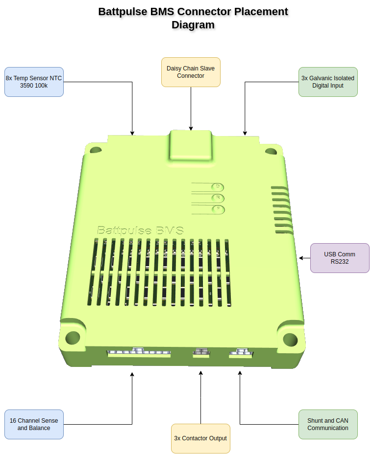
A) Sense & Balance — 43025-1800 (18-pin)
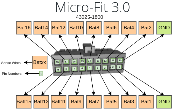
| Pin | Signal | Pin | Signal |
|---|
| 1 | GND | 10 | GND |
| 2 | Bat1 | 11 | Bat2 |
| 3 | Bat3 | 12 | Bat4 |
| 4 | Bat5 | 13 | Bat6 |
| 5 | Bat7 | 14 | Bat8 |
| 6 | Bat9 | 15 | Bat10 |
| 7 | Bat11 | 16 | Bat12 |
| 8 | Bat13 | 17 | Bat14 |
| 9 | Bat15 | 18 | Bat16 |
B) Contactor Output — 43025-0400 (4-pin)
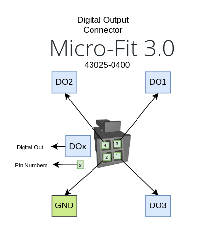
| Pin | Signal | Description |
|---|
| 1 | DO3 | Digital Output 3 (auxiliary) |
| 2 | GND | Ground reference |
| 3 | DO1 | Digital Output 1 (charge contactor) |
| 4 | DO2 | Digital Output 2 (discharge contactor) |
C) Shunt & CAN Communication — 43025-0600 (6-pin)
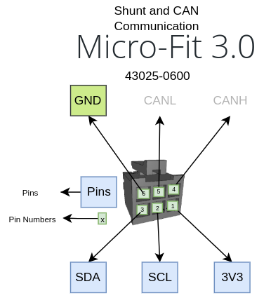
| Pin | Signal | Description |
|---|
| 1 | 3V3 | 3.3 V reference (shunt power) |
| 2 | SCL | I²C clock (shunt) |
| 3 | SDA | I²C data (shunt) |
| 4 | CAN-H | CAN Bus High |
| 5 | CAN-L | CAN Bus Low |
| 6 | GND | Ground reference (shunt) |
D) Digital Input — 43025-0600 (6-pin)
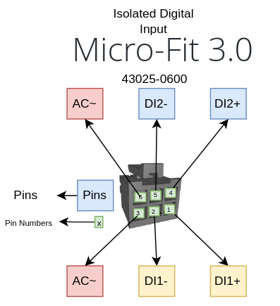
| Pin | Signal | Description |
|---|
| 1 | DI1+ | Digital Input 1 positive (24–70 V) |
| 2 | DI1− | Digital Input 1 negative |
| 3 | AC | AC detect input 1 |
| 4 | DI2+ | Digital Input 2 positive (24–70 V) |
| 5 | DI2− | Digital Input 2 negative |
| 6 | AC | AC detect input 2 |
E) Temperature Sensor — 43025-1000 (10-pin)
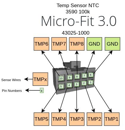
| Pin | Signal | Description |
|---|
| 1 | TMP1 | NTC Probe 1 |
| 2 | TMP2 | NTC Probe 2 |
| 3 | TMP3 | NTC Probe 3 |
| 4 | TMP4 | NTC Probe 4 |
| 5 | TMP5 | NTC Probe 5 |
| 6 | GND | Ground (shared) |
| 7 | GND | Ground (shared) |
| 8 | TMP8 | NTC Probe 8 |
| 9 | TMP7 | NTC Probe 7 |
| 10 | TMP6 | NTC Probe 6 |
Connector Summary
| Connector | Molex P/N (Housing) | Pins | Function |
|---|
| Sense & Balance | 43025-1800 | 18 | Cell voltage sense + passive balancing |
| Contactor Output | 43025-0400 | 4 | DO1, DO2, DO3 + GND |
| Shunt & CAN | 43025-0600 | 6 | Shunt I²C + CAN-H/CAN-L + GND |
| Digital Input | 43025-0600 | 6 | DI1, DI2, AC detect × 2 |
| Temperature | 43025-1000 | 10 | 8 NTC probes + 2 GND |
8. Mechanical & Environmental
| Parameter | Value |
|---|
| PCB Layers | Multi-layer |
| Mounting | 4 × M3 mounting holes |
| Operating Temperature | −20 to +60 °C |
| Storage Temperature | −40 to +85 °C |
| Humidity | 5–95% RH (non-condensing) |
| Conformal Coating | Optional (contact sales) |
ℹ️ Dimensions
For exact board dimensions and mounting hole positions, refer to the mechanical drawing supplied with your order or contact info@battpulse.com.
9. Daisy-Chain & High-Voltage Packs
For battery packs exceeding 16S, the BattPulse Leader BMS supports a daisy-chain architecture with one master unit and up to 15 slave units.
| Parameter | Value |
|---|
| Maximum Slave Units | 15 |
| Total Cell Count | Up to 126S (16S × ~8 units, configurable) |
| Communication (inter-board) | Isolated serial daisy-chain |
| Target Voltage Class | 400 V / 800 V packs |
| Isolation | Galvanic isolation between stack levels |
💡 Daisy-Chain Configuration
Each slave unit monitors its own 6–16S segment and reports cell data to the master via the daisy-chain bus. The master aggregates all data and exposes it on the CAN Bus and WiFi interfaces. Contact info@battpulse.com for daisy-chain wiring details and high-voltage pack design guidance.
10. Ecosystem & Compatibility
BattPulse Display 7″
The BattPulse Leader BMS is natively compatible with the BattPulse BMS Display 7″. Both CAN and WiFi work out of the box:
| Connection | Setup | Data Rate |
|---|
| CAN Bus | Wire CAN-H/CAN-L. Match baud rate. Data appears automatically. | 100 ms (10 Hz) |
| WiFi | Same network. Enter BMS IP. Select BattPulse type. | ~250 ms (~4 Hz) |
Third-Party Integration
The open Developer API (CAN + WiFi) allows integration with:
- Custom LCD/TFT displays and HMIs
- Vehicle ECUs and inverters (CAN interface)
- Data loggers (CAN or WiFi)
- SCADA and industrial monitoring systems
- Custom mobile apps and web dashboards (WiFi/JSON)
- Home automation and IoT platforms
ℹ️ Open API for Integrators
The BattPulse Developer API is open to integrators of all sizes. Full CAN frame layouts and WiFi JSON schemas are documented in the Developer API Reference.
🛒 Complete BMS + Display Solution
Pair the BattPulse Leader BMS with the BattPulse Display 7″ for a plug-and-play battery monitoring system.
🔋 Get the BMS →
🖥 Get the Display →
11. Ordering Information
| Model | Description | Includes |
|---|
| BP-BMS-001 |
BattPulse Leader BMS
(single master unit) |
BMS board + 5 mate connector housings with crimp pins (18-pin, 4-pin, 6-pin × 2, 10-pin) |
Accessories (Sold Separately)
| Item | Description |
|---|
| NTC Probes | 100K 3950 NTC temperature probes (pack of 4 or 8) |
| BP-DSP-7001 | BattPulse BMS Display 7″ — touchscreen LCD monitor |
| Shunt Sensor | High-precision current shunt (rated for your application current) |
| Slave Units | Additional BMS boards for daisy-chain configurations (contact sales) |
How to Order
12. Document Revision History
| Revision | Date | Changes |
|---|
| 1.0 | March 2026 | Initial release |