BattPulse
Securing the Energy Transformation
Leader Battery Management System
Quick Start Guide
6S–126S BMS + CAN + WiFi
Get your BattPulse Leader BMS up and running.
Connectors, wiring, and first power-on.
Contents
- What’s in the Box
- BMS Overview
- Connectors & Pinouts
- Wiring Steps
- First Power-On
- Connecting a Display or Logger
- Safety Notes
1. What’s in the Box
| Item | Qty | Notes |
|---|
| BattPulse Leader BMS board | 1 | — |
| Sense & Balance mate connector (Micro-Fit 3.0 housing, 18-pin) with crimp pins | 1 | 43025-1800 housing + crimp pins |
| Contactor Output mate connector (Micro-Fit 3.0 housing, 4-pin) with crimp pins | 1 | 43025-0400 housing + crimp pins |
| Shunt & CAN mate connector (Micro-Fit 3.0 housing, 6-pin) with crimp pins | 1 | 43025-0600 housing + crimp pins |
| Digital Input mate connector (Micro-Fit 3.0 housing, 6-pin) with crimp pins | 1 | 43025-0600 housing + crimp pins |
| Temperature Sensor mate connector (Micro-Fit 3.0 housing, 10-pin) with crimp pins | 1 | 43025-1000 housing + crimp pins |
ℹ️ Accessories Available Separately
- NTC Temperature Probes: 100K 3950 NTC probes. Up to 8 can be connected. Purchase separately.
- BattPulse Display 7″: Plug-and-play touchscreen display for your BMS. Get it here →
⚠️ Before You Start
- Use appropriate gauge wire for your application current.
- Read the Safety Notes section before wiring.
2. BMS Overview
Key Specifications
| Feature | Specification |
|---|
| Cell Count | 6S – 126S (configurable) |
| Supported Chemistry | Lithium-ion, LiFePO4 (LFP), Li-NMC, Li-NCA, LTO |
| Balancing | Passive cell balancing, up to 1 A per cell |
| Cell Measurement | 16-bit high-accuracy analogue front-end |
| Current Measurement | High-precision shunt-based sensor |
| Continuous Current | Up to 400 A |
| Temperature Probes | Up to 8 external NTC probes (100K 3950) |
| Digital Inputs | 3 × galvanically isolated (24–70 V DC and AC 230V) |
| Contactor Outputs | 3 × digital outputs (DO1, DO2, DO3) |
| Communication | CAN Bus (CAN 2.0B, 250-500-1000 kbps) + WiFi (HTTP/JSON) |
| Daisy Chain | Up to 15 slave units (for 400 V / 800 V packs) |
| Connector System | Micro-Fit 3.0 locking connectors throughout |
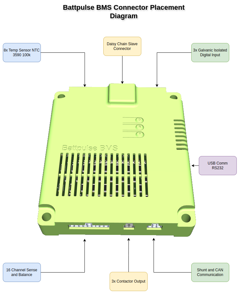
Connector Placement
All connectors are located around the edges of the BMS board. Refer to the diagram below for placement:
3. Connectors & Pinouts
All connectors on the BattPulse Leader BMS use the Molex Micro-Fit 3.0 system — locking, automotive-grade connectors rated for high reliability and vibration resistance.
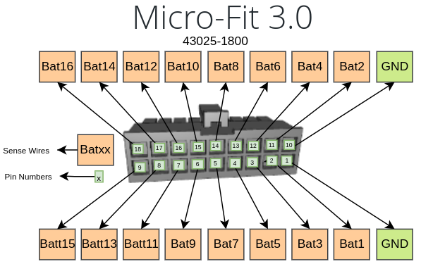
A) Sense & Balance Connector
Micro-Fit 3.0 — 43025-1800 (18-pin)
| Pin | Signal | Pin | Signal |
|---|
| 1 | GND | 10 | GND |
| 2 | Bat1 | 11 | Bat2 |
| 3 | Bat3 | 12 | Bat4 |
| 4 | Bat5 | 13 | Bat6 |
| 5 | Bat7 | 14 | Bat8 |
| 6 | Bat9 | 15 | Bat10 |
| 7 | Bat11 | 16 | Bat12 |
| 8 | Bat13 | 17 | Bat14 |
| 9 | Bat15 | 18 | Bat16 |
💡 Only Wire Active Cells
For packs smaller than 16S, only wire the cells you use. Example: 8S pack → wire GND + Bat1 through Bat8. Leave remaining pins empty. Connect the Bat8 to Bat16 to finalise. Batt16 will be connected to the highest cell always.
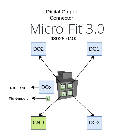
B) Contactor Output Connector
Micro-Fit 3.0 — 43025-0400 (4-pin)
| Pin | Signal | Description |
|---|
| 1 | DO3 | Digital Output 3 (auxiliary) |
| 2 | GND | Ground reference |
| 3 | DO1 | Digital Output 1 (charge contactor) |
| 4 | DO2 | Digital Output 2 (discharge contactor) |
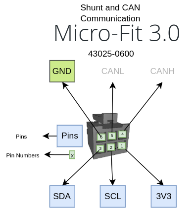
C) Shunt & CAN Communication Connector
Micro-Fit 3.0 — 43025-0600 (6-pin)
| Pin | Signal | Description |
|---|
| 1 | 3V3 | 3.3 V reference (shunt power) |
| 2 | SCL | I2C clock (shunt communication) |
| 3 | SDA | I2C data (shunt communication) |
| 4 | CAN-H | CAN Bus High signal |
| 5 | CAN-L | CAN Bus Low signal |
| 6 | GND | Ground reference (shunt) |
⚠️ CAN Bus Has No Dedicated GND Pin
The GND pin (pin 6) is the shunt ground reference. For CAN communication, only CAN-H and CAN-L are needed. If you need GND pin for CAN as a refferance for some reason you can use the pin 6 GND for this purpose.
D) Digital Input Connector
Micro-Fit 3.0 — 43025-0600 (6-pin)
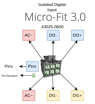
| Pin | Signal | Description |
|---|
| 1 | DI1+ | Digital Input 1 positive (24–70 V) |
| 2 | DI1− | Digital Input 1 negative |
| 3 | AC | AC detect input 1 |
| 4 | DI2+ | Digital Input 2 positive (24–70 V) |
| 5 | DI2− | Digital Input 2 negative |
| 6 | AC | AC detect input 2 |
🔴 Hardware Note
Confirm the digital input wiring on your board before connecting high-voltage signals. AC signal on DI1 and DI2 would create problem on the board. DI2- and DI2+ may be swapped on your hardware version if you have any problem on making DI2 please swap the + and - and try again. Dont worry inputs are protected on swapping the pins.
E) Temperature Sensor Connector
Micro-Fit 3.0 — 43025-1000 (10-pin)
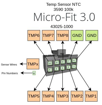
| Pin | Signal | Description |
|---|
| 1 | TMP1 | NTC Probe 1 |
| 2 | TMP2 | NTC Probe 2 |
| 3 | TMP3 | NTC Probe 3 |
| 4 | TMP4 | NTC Probe 4 |
| 5 | TMP5 | NTC Probe 5 |
| 6 | GND | Ground (shared) |
| 7 | GND | Ground (shared) |
| 8 | TMP8 | NTC Probe 8 |
| 9 | TMP7 | NTC Probe 7 |
| 10 | TMP6 | NTC Probe 6 |
ℹ️ NTC Probes
Use 100K 3950 NTC thermistors. Each probe connects between its TMP pin and GND. The BMS supports up to 8 probes — configure the probe count in BMS settings. NTC probes are purchased separately.
4. Wiring Steps
🔴 High Voltage Warning
Lithium battery packs can deliver lethal voltages and currents. Disconnect the battery pack before wiring. Follow all safety procedures.
1 Prepare the Connectors
- Strip wire ends and crimp them into the supplied Micro-Fit 3.0 crimp pins using the appropriate crimping tool.
- Insert crimped wires into the mate connector housings according to the pinout tables above.
- Verify each pin — a click confirms the pin is locked in the housing.
2 Wire the Sense & Balance Connector
- Connect the cell balance leads from your battery pack to the Sense & Balance connector.
- Pin 1 (GND) connects to the pack negative terminal.
- Bat1 connects to the top of cell 1, Bat2 to the top of cell 2, and so on.
- For packs smaller than 16S, only wire the cells in use.
3 Wire the Shunt & CAN Connector
- Connect the current shunt sensor to pins 1–3 (3V3, SCL, SDA) and pin 6 (GND).
- Connect CAN-H (pin 4) and CAN-L (pin 5) to your CAN bus network or display.
- Turn the jumper to add a 120 Ω termination resistor at each end of the CAN bus if not already done.
4 Wire the Contactor Outputs (They are negative side switching mosfets)
- Connect DO1, DO2, DO3 to your contactors or relays as needed. your relay will be powered directly with the rated voltage and GND side of the relay will be connected to the DO1 or DO2
- Pin 2 (GND) is the ground reference for the outputs. (Optional)
5 Connect Temperature Probes (Optional)
- Connect each NTC probe between its TMP pin and one of the GND pins (pin 6 or 7).
- Use 100K 3950 NTC thermistors.
- Configure the probe count in BMS settings to match the number of connected probes.
5. First Power-On
Power-On Checklist
- All balance leads are correctly wired and seated
- Shunt sensor is connected (3V3, SCL, SDA, GND)
- CAN bus wiring is correct (CAN-H, CAN-L) with termination
- No short circuits between adjacent pins
- Battery pack is within safe voltage range
1 Apply Power
The BMS is powered from the battery pack through the Sense & Balance connector. Once the balance leads are connected to a charged pack, the BMS will power on automatically.
2 Verify Operation
- The on-board LEDs will indicate power and communication status.
- CAN bus frames begin transmitting immediately at 100 ms intervals (see Developer API Reference for frame details).
- If a BattPulse Display 7″ is connected via CAN, data will appear on the display automatically.
3 Configure BMS Settings
Access the BMS web interface to configure:
- Cell count (6S–16S)
- Number of NTC temperature probes
- Current sensor calibration
- Overvoltage / undervoltage / overtemperature thresholds
- Contactor output behaviour
6. Connecting a Display or Logger
CAN Bus Connection (Recommended)
The fastest and simplest way to view BMS data. The BattPulse Display 7″ is natively compatible:
- Wire CAN-H and CAN-L from the BMS connector to your display or data logger.
- Ensure 120 Ω termination at both ends of the bus.
- Set baud rate to 500 kbps.
- Data appears automatically — no configuration needed.
WiFi Connection
Connect your device (display, laptop, phone) to the same WiFi network as the BMS. Then write the BMS IP on the browser. It will start polling the data over http:
- Endpoint:
http://<BMS_IP>/JsonHandle
- Method: POST with JSON body
- Request types:
{"type":"dashboard"} or {"type":"cellStates"}
See the Developer API Reference for complete protocol details and code examples.
🛒 Complete BMS + Display Solution
Pair the BattPulse Leader BMS with the BattPulse Display 7″ for a plug-and-play battery monitoring system.
🔋 Get the BMS →
🖥 Get the Display →
7. Common Questions & Troubleshooting
Q: I connected the USB cable but I can't see anything at 115200 baud — why?
Most USB problems are caused by the cable or drivers, not the BMS. Try these steps in order:
- Try a different USB cable — some cables only provide power and do not carry data.
- On Windows, install the CP210x USB-to-UART driver if your OS does not automatically recognise the device. On most Linux distributions no additional driver is required.
- Confirm you are using the correct serial settings in your terminal program. The BMS console (if present) typically uses 115200 8N1; however, some tools/devices may use different rates — double-check the product notes.
- Test with another PC or USB port to rule out host-side USB faults.
Q: CAN Bus doesn't work — what should I check?
Use the checklist below to find common CAN bus problems:
- Baud rate: Ensure both devices (BMS and display/logger) are set to the same baud rate. The BattPulse system uses 500 kbps by default.
- Termination resistors: A proper CAN bus requires a 120 Ω termination resistor at each physical end of the bus. Verify that both ends have 120 Ω in place.
- On-board termination switches: The BMS includes internal termination; some displays have a switch on the back to enable/disable termination. If the display is acting as one end of the bus, enable its 120 Ω switch. If both ends have termination enabled twice (two resistors at same end), you will get incorrect loading — make sure exactly one 120 Ω is present at each physical end.
- Wiring: Confirm CAN-H is connected to CAN-H and CAN-L to CAN-L on every device. Keep the CAN pair twisted and avoid long stubs.
- Bus length & topology: Use a linear bus topology; avoid star or long unterminated stubs.
- Ground reference: CAN is differential, but if an external device requires a ground reference connect chassis or ground appropriately (use shunt GND if needed).
- Transceiver power: Ensure both transceivers are powered (3.3 V or 5 V as required).
- Tools: Use a CAN adapter or analyser (e.g., Peak, Kvaser, or a USB-CAN dongle) to verify traffic and fault conditions.
Q: Where is a quick CAN checklist?
See the CAN Bus checklist above and the short link in the Shunt & CAN section for quick reference.
Q: OLED screen is flickering — what can I do?
Flicker is commonly caused by electrical noise or an unstable power source. Try these mitigations:
- Move the OLED and its cables away from noisy power supplies (AC/DC adapters, DC/DC converters, motor controllers).
- Use twisted-pair wiring and shielded cable for the display signals where possible; keep power and signal cables separated from noisy bundles.
- Add ferrite beads on the display power cable and ensure good grounding practice.
- Try powering the display from a separate, low-noise supply to see if the problem follows the supply.
- Check and secure all ground connections — poor grounds are a common source of flicker.
8. Safety Notes
🔴 Critical Safety Information
- Disconnect the battery pack before wiring. Lithium batteries can deliver dangerous voltages and currents.
- Do not short-circuit any balance leads or connector pins.
- Use appropriate wire gauge for your pack current.
- Verify all connections before power-on. Incorrect wiring can permanently damage the BMS.
- Do not exceed the rated voltage range of the BMS (6S–126S).
- NTC probes (100K 3950) are required for temperature protection. Without probes, overtemperature faults cannot be detected on the battery cells.
⚠️ DI2 Pin Reversal
Current production boards have DI2+ and DI2− reversed on the PCB silkscreen. See the
Digital Input Connector section for the correct wiring.