Complete protocol reference for the BattPulse Leader BMS.
CAN Bus telemetry, WiFi HTTP/JSON API, command protocol, and code examples.
The BattPulse Leader BMS is a professional-grade, automotive-rated battery management system. It features a high-accuracy 16-bit analogue front-end for cell monitoring, high-current shunt-based current measurement, and a powerful dual-core microcontroller. It supports up to 126S lithium battery configurations (see product notes) with real-time cell monitoring, balancing, overcurrent protection, and multiple temperature probes.
The BMS exposes its telemetry data and accepts commands through two interfaces:
| Method | Transport | Speed | Best For |
|---|---|---|---|
| CAN Bus | CAN 2.0B (11-bit) | 100 ms cycle (10 Hz) | BattPulse Display 7″, LCD displays, data loggers, vehicle ECUs, industrial systems |
| WiFi | HTTP POST / JSON | ~250 ms cycle | Web dashboards, mobile apps, BattPulse Display 7″, remote monitoring |
This API reference is for system integrators, display developers, and embedded engineers who want to read BMS data or send commands to the BattPulse Leader BMS. Use these protocols to build custom dashboards, data loggers, or connect the BattPulse Display 7″.
Ready to get started? Order the BattPulse Leader BMS directly from our store.
battpulse.com/product/battpulse-leader-battery-management-system →| Parameter | Value |
|---|---|
| Standard | CAN 2.0B (11-bit standard identifiers) |
| Baud Rate | 500 kbps |
| Byte Order | Little-endian (LSB first) |
| Transceiver | Automotive-grade CAN transceiver (3.3 V logic) |
| Termination | 120 Ω required at each end of the bus |
| Cycle Time | 100 ms (all frames transmitted every cycle) |
| Frame Format | Standard (11-bit), no extended, no RTR |
The CAN bus shares a connector with the shunt interface. See the Shunt and CAN Communication connector (Micro-Fit 3.0 — 43025-0600):
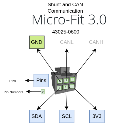
| Pin | Signal | Description |
|---|---|---|
| 1 | 3V3 | 3.3 V reference (shunt power) |
| 2 | SCL | I2C clock (shunt) |
| 3 | SDA | I2C data (shunt) |
| 4 | CAN-H | CAN High signal |
| 5 | CAN-L | CAN Low signal |
| 6 | GND | Ground (shunt reference) |
| CAN ID(s) | Direction | Frame Name | DLC | Cycle |
|---|---|---|---|---|
0x300 |
BMS → External | Pack Status (V, I, SOC, Status) | 7 | 100 ms |
0x301 |
BMS → External | Status Extended (MaxC, MinC, Temp extremes) | 8 | 100 ms |
0x302 |
BMS → External | Energy (capacity, SOH) — Reserved, not yet sent | — | — |
0x330 – 0x337 |
BMS → External | Cell Voltages (2 cells per frame) | 4 | 100 ms |
0x350 – 0x351 |
BMS → External | Temperature Probes (4 per frame) | 8 | 100 ms |
0x360 |
BMS → External | I/O State (FETs, Balancing, Digital Inputs) | 2 | 100 ms |
0x370 |
BMS → External | Fault / Warning Bitmasks | 4 | 100 ms |
0x3A0 |
External → BMS | Command Frame (Restart) | 5 | On demand |
| Byte | Type | Scale | Unit | Description |
|---|---|---|---|---|
| 0–1 | uint16 | ÷ 100 | V | Pack Voltage — sum of all cell voltages (e.g. 5120 = 51.20 V) |
| 2–3 | int16 | ÷ 10 | A | Pack Current (+ = charging, − = discharging) |
| 4–5 | uint16 | ÷ 10 | % | SOC (e.g. 850 = 85.0%) |
| 6 | uint8 | — | — | Status: 0=Idle, 1=Charging, 2=Discharging, 3=Fault |
| Value | Meaning | Condition |
|---|---|---|
| 0 | Idle | Current within ±0.5 A dead-band |
| 1 | Charging | Current > +0.5 A |
| 2 | Discharging | Current < −0.5 A |
| 3 | Fault | Any fault flag active (overvoltage, undervoltage, overtemp, powerdown) |
Raw byte example — Pack at 51.20 V, charging at 15.0 A, SOC 85.0%:
Byte:  [0]   [1]   [2]   [3]   [4]   [5]   [6]
Hex:   0x00  0x14  0x96  0x00  0x52  0x03  0x01
       <--5120-->  <--150--->  <--850--->  Status=Charging
| Byte | Type | Scale | Unit | Description |
|---|---|---|---|---|
| 0–1 | uint16 | ÷ 1000 | V | Highest cell voltage (e.g. 3650 = 3.650 V) |
| 2–3 | uint16 | ÷ 1000 | V | Lowest cell voltage (e.g. 3580 = 3.580 V) |
| 4–5 | int16 | ÷ 10 | °C | Highest temperature across all probes |
| 6–7 | int16 | ÷ 10 | °C | Lowest temperature across all probes |
This frame is defined in the protocol but not yet transmitted. Capacity (Ah), remaining capacity, cycle count, and State of Health (SOH) are not available in the current firmware version. Displays should show “—” for these fields.
When implemented in a future firmware update, the frame layout will be:
| Byte | Type | Scale | Unit | Description |
|---|---|---|---|---|
| 0–1 | uint16 | ÷ 10 | Ah | Total capacity |
| 2–3 | uint16 | ÷ 10 | Ah | Remaining capacity |
| 4–5 | uint16 | × 1 | — | Cycle count |
| 6 | uint8 | × 1 | % | State of Health |
| Byte | Type | Scale | Unit | Description |
|---|---|---|---|---|
| 0–1 | uint16 | ÷ 1000 | V | Cell N voltage (e.g. 3650 = 3.650 V) |
| 2–3 | uint16 | ÷ 1000 | V | Cell N+1 voltage |
Cell-to-Frame mapping:
| CAN ID | Cells | CAN ID | Cells |
|---|---|---|---|
0x330 | Cell 1, 2 | 0x334 | Cell 9, 10 |
0x331 | Cell 3, 4 | 0x335 | Cell 11, 12 |
0x332 | Cell 5, 6 | 0x336 | Cell 13, 14 |
0x333 | Cell 7, 8 | 0x337 | Cell 15, 16 |
0x330–0x333 only.0x0000.Each frame carries 4 temperature probes as int16 values:
| Byte | Type | Scale | Unit | Description |
|---|---|---|---|---|
| 0–1 | int16 | ÷ 10 | °C | Probe slot 0 (or 4) |
| 2–3 | int16 | ÷ 10 | °C | Probe slot 1 (or 5) |
| 4–5 | int16 | ÷ 10 | °C | Probe slot 2 (or 6) |
| 6–7 | int16 | ÷ 10 | °C | Probe slot 3 (or 7) |
| CAN ID | Probes |
|---|---|
0x350 | T1, T2, T3, T4 |
0x351 | T5, T6, T7, T8 |
Temperature slots are populated in a fixed priority order. Absent sensors are skipped — remaining probes shift up.
| Priority | Sensor | Condition |
|---|---|---|
| 1 | Internal die temperature | Always present |
| 2 | Board temperature sensor | Only on V2/V3 hardware; skipped if unavailable |
| 3 | Shunt die temperature | Only when I2C shunt mode is active |
| 4–11 | External NTC probes 1–8 | Only if configured (NTC count > 0) |
Example — 4-probe configuration (Die=32°C, Shunt=19°C, NTC1=18°C, NTC2=19°C):
Frame 0x350 raw bytes:
  Byte 0: 0x40  |  T1 = 320 (int16 LE) -> 32.0°C  (Die Temp)
  Byte 1: 0x01  |
  Byte 2: 0xBE  |  T2 = 190 (int16 LE) -> 19.0°C  (Shunt Temp)
  Byte 3: 0x00  |
  Byte 4: 0xB4  |  T3 = 180 (int16 LE) -> 18.0°C  (NTC_1)
  Byte 5: 0x00  |
  Byte 6: 0xBE  |  T4 = 190 (int16 LE) -> 19.0°C  (NTC_2)
  Byte 7: 0x00  |
| Byte | Type | Description |
|---|---|---|
| 0–1 | uint16 (LE) | I/O bitmask |
| Bit | Name | Meaning |
|---|---|---|
| 0 | CHG | Charge contactor (1 = ON, 0 = OFF) |
| 1 | DSC | Discharge contactor (1 = ON, 0 = OFF) |
| 2 | BAL | Cell balancing active (1 = Active) |
| 3 | DI1 | Digital Input 1 — galvanically isolated (1 = active) |
| 4 | DI2 | Digital Input 2 — galvanically isolated (1 = active) |
| 5 | DI3 | Digital Input 3 — galvanically isolated (1 = active) |
| 6–15 | — | Reserved for future expansion |
1 in the CAN bitmask means the input is active.| Byte | Type | Description |
|---|---|---|
| 0–1 | uint16 (LE) | Warning bitmask (informational — yellow indicator) |
| 2–3 | uint16 (LE) | Fault bitmask (critical — red indicator, forces Status = FAULT) |
Warning bits:
| Bit | Meaning |
|---|---|
| 0 | General BMS alarm |
Fault bits:
| Bit | Meaning |
|---|---|
| 0 | Cell overvoltage (cell exceeds OV cutoff) |
| 1 | Cell undervoltage (cell below UV cutoff) |
| 2 | Over-temperature (probe exceeds temperature cutoff) |
| 3 | Emergency power-down |
When any fault bit is set, the Status byte in frame 0x300 is forced to 3 (Fault). Displays should show a red fault banner with the hex fault code.
This is the only frame the BMS accepts from external devices. It uses a two-step ARM + EXECUTE safety protocol to prevent accidental commands from CAN bus noise or software bugs.
| Byte | Type | Description |
|---|---|---|
| 0 | uint8 | Command: 0x01 = ARM, 0x02 = EXECUTE |
| 1–4 | bytes | Safety key: { 0x52, 0x53, 0x54, 0x52 } (“RSTR”) |
| Step | Byte 0 | Action |
|---|---|---|
| 1. ARM | 0x01 | BMS enters armed state. A 2-second execution window opens. |
| 2. EXECUTE | 0x02 | If armed and within 2 seconds → BMS soft-restarts. Otherwise → ignored. |
Every command frame (both ARM and EXECUTE) MUST include the 4-byte safety key { 0x52, 0x53, 0x54, 0x52 } at bytes 1–4. This prevents:
Frames with an incorrect key are silently rejected.
 External Device                  BattPulse BMS
  |                                |
  |-- 0x3A0 [01 52 53 54 52] --->|  ARM - armed state, 2s timer starts
  |                                |
  |     (within 2 seconds)         |
  |                                |
  |-- 0x3A0 [02 52 53 54 52] --->|  EXECUTE - BMS restarts!
  |                                |
  |        ~~~ BMS reboots ~~~     |
  |        (2-4 second gap)        |
  |                                |
  |<-- 0x300, 0x330, etc. --------|  BMS back online, CAN TX resumes
| Scenario | Result |
|---|---|
| ARM → EXECUTE (within 2s) | BMS restarts |
| ARM → (wait > 2s) → EXECUTE | Ignored (timer expired) |
| EXECUTE without prior ARM | Ignored |
| ARM → ARM → EXECUTE (within 2s) | BMS restarts (second ARM resets timer) |
| ARM only — EXECUTE never sent | Armed state expires silently after 2s |
| ARM with wrong key → EXECUTE with correct key | Ignored (ARM was rejected) |
/* Parse a received 0x300 frame from the BattPulse Leader BMS.
 * Adapt to your CAN library and microcontroller platform. */

void parsePackStatus(const uint8_t *data, uint8_t dlc) {
    if (dlc < 7) return;

    uint16_t rawV   = data[0] | (data[1] << 8);   // little-endian
    int16_t  rawI   = data[2] | (data[3] << 8);
    uint16_t rawSOC = data[4] | (data[5] << 8);
    uint8_t  status = data[6];

    float packVoltage = rawV / 100.0;    // Volts
    float packCurrent = rawI / 10.0;     // Amps (+ = charging)
    float soc         = rawSOC / 10.0;   // Percent

    printf("Pack: %.2fV  %.1fA  SOC: %.1f%%  Status: %d\n",
           packVoltage, packCurrent, soc, status);
}
/* Send the two-step ARM + EXECUTE restart command to the BMS.
 * Adapt to your CAN driver / controller. */

void sendBmsRestart() {
    can_frame_t cmd;
    memset(&cmd, 0, sizeof(cmd));
    cmd.id  = 0x3A0;
    cmd.dlc = 5;

    // Step 1: ARM
    cmd.data[0] = 0x01;    // ARM restart
    cmd.data[1] = 0x52;    // Safety key: 'R'
    cmd.data[2] = 0x53;    // Safety key: 'S'
    cmd.data[3] = 0x54;    // Safety key: 'T'
    cmd.data[4] = 0x52;    // Safety key: 'R'
    can_send(&cmd);

    delay_ms(200);  // Brief pause between steps

    // Step 2: EXECUTE
    cmd.data[0] = 0x02;    // EXECUTE restart
    can_send(&cmd);

    printf("Restart command sent - BMS will reboot in ~2-4 seconds\n");
}
/* Parse cell voltage frames 0x330-0x337.
 * Call this for each received cell voltage frame. */

float cellVoltages[16];
int   cellCount = 0;

void parseCellVoltageFrame(uint16_t canId, const uint8_t *data) {
    int offset = canId - 0x330;
    if (offset < 0 || offset > 7) return;

    int cell1 = offset * 2;
    int cell2 = cell1 + 1;

    uint16_t raw1 = data[0] | (data[1] << 8);
    uint16_t raw2 = data[2] | (data[3] << 8);

    cellVoltages[cell1] = raw1 / 1000.0;  // Volts
    if (raw2 > 0) {
        cellVoltages[cell2] = raw2 / 1000.0;
        if (cell2 + 1 > cellCount) cellCount = cell2 + 1;
    } else {
        if (cell1 + 1 > cellCount) cellCount = cell1 + 1;
    }
}
The BattPulse Leader BMS runs a built-in web server on port 80. External devices (displays, dashboards, mobile apps) connect to the BMS WiFi network and poll the HTTP API.
| Parameter | Value |
|---|---|
| Transport | HTTP 1.1 |
| Content-Type | text/plain (request) → JSON (response) |
| Endpoint | http://<BMS_IP>/JsonHandle |
| Method | POST (with JSON body) |
| Response | JSON array — [{ ... }] |
| Port | 80 |
The BMS supports these request types via the "type" field in the JSON body:
dashboard — returns pack status, temperatures, I/O statescellStates — returns individual cell voltages and colours/JsonHandle endpoint automatically, alternating between dashboard and cellStates requests at ~250 ms intervals.
Get the BattPulse Display 7″ →
Request:
POST /JsonHandle HTTP/1.1
Content-Type: text/plain

{"type":"dashboard"}
Response:
[{
  "type": "dashboard",
  "status": {
    "current": -12.5,
    "event": "Ready   ",
    "SoC": "%85",
    "PackV": "51.20",
    "MaxC": "3.65",
    "MinC": "3.60"
  },
  "TempProbes": {
    "Die Temp": 32,
    "ShuntTemp": 19,
    "Aux_1": 18,
    "Aux_2": 19
  },
  "IO_States": {
    "IN1": 0,
    "IN2": 0,
    "DO1": 1,
    "DO2": 1,
    "CHG": 1,
    "DSC": 1
  }
}]
Field Reference:
| Field | Type | Description |
|---|---|---|
status.current | float | Pack current in amps (negative = charging, positive = discharging) |
status.event | string | Last event message (e.g. “Ready”, “Charging limit on 50”) |
status.SoC | string | State of charge with % prefix (e.g. “%85”) |
status.PackV | string | Pack voltage as formatted string |
status.MaxC | string | Highest cell voltage as formatted string |
status.MinC | string | Lowest cell voltage as formatted string |
TempProbes.* | object | Named temperature probes — key = sensor name, value = °C (integer) |
IO_States.* | object | Named I/O states — key = I/O name, value = 0 (OFF) or 1 (ON) |
TempProbes object only includes active sensors. Internal sensors that are not present are omitted. External NTC probes appear as Aux_1, Aux_2, etc., based on the configured probe count.
Request:
POST /JsonHandle HTTP/1.1
Content-Type: text/plain

{"type":"cellStates"}
Response (example: 7S pack):
[{
  "type": "cellStates",
  "cells": {
    "Cell1": 3.650,
    "Cell2": 3.645,
    "Cell3": 3.660,
    "Cell4": 3.640,
    "Cell5": 3.655,
    "Cell6": 3.648,
    "Cell7": 3.652
  },
  "colors": {
    "1": "green",
    "2": "green",
    "3": "green",
    "4": "green",
    "5": "green",
    "6": "green",
    "7": "green"
  },
  "status": {
    "current": -12.5
  },
  "IO_States": {
    "IN1": 0,
    "IN2": 0,
    "DO1": 1,
    "DO2": 1,
    "CHG": 1,
    "DSC": 1
  }
}]
Field Reference:
| Field | Type | Description |
|---|---|---|
cells | object | Cell name → voltage pairs. Cell count = number of keys (6–126). |
colors | object | Cell index (1-based) → colour string. Colour-coded by BMS based on OV/UV thresholds. |
status.current | float | Pack current (same convention as dashboard) |
IO_States | object | I/O states (same format as dashboard) |
import requests
import json

BMS_IP = "192.168.1.100"
URL = f"http://{BMS_IP}/JsonHandle"

# Get dashboard data
resp = requests.post(URL, data=json.dumps({"type": "dashboard"}))
data = resp.json()[0]

packV   = float(data["status"]["PackV"])
current = data["status"]["current"]
soc     = data["status"]["SoC"]

print(f"Pack: {packV}V  Current: {current}A  SOC: {soc}")

# Get cell voltages
resp = requests.post(URL, data=json.dumps({"type": "cellStates"}))
cells = resp.json()[0]["cells"]

for name, voltage in cells.items():
    print(f"  {name}: {voltage:.3f}V")
/* Adapt this to your embedded HTTP client library. */

void pollBmsDashboard() {
    http_client_t http;
    http_init(&http, "http://192.168.1.100/JsonHandle");
    http_set_header(&http, "Content-Type", "text/plain");

    int code = http_post(&http, "{\"type\":\"dashboard\"}");
    if (code == 200) {
        const char* payload = http_get_response(&http);
        // Parse JSON response - first element of array
        // Extract status.current, status.SoC, status.PackV, etc.
        printf("Response: %s\n", payload);
    }
    http_close(&http);
}
| Field | CAN Source | WiFi Source | Range |
|---|---|---|---|
| Pack Voltage | 0x300 bytes 0–1 | status.PackV | 0–120 V |
| Pack Current | 0x300 bytes 2–3 | status.current | −500 to +500 A |
| SOC | 0x300 bytes 4–5 | status.SoC | 0–100% |
| Status | 0x300 byte 6 | status.event | 0–3 (enum) |
| Max Cell Voltage | 0x301 bytes 0–1 | status.MaxC | 0–5 V |
| Min Cell Voltage | 0x301 bytes 2–3 | status.MinC | 0–5 V |
| Cell Voltages | 0x330–0x337 | cells.* | 6–126 cells (pack-dependent), 0–5 V each |
| Temperatures | 0x350–0x351 | TempProbes.* | 1–8 probes, −50 to +150 °C |
| I/O States | 0x360 | IO_States.* | CHG, DSC, BAL, DI1, DI2, DI3 |
| Faults | 0x370 | status.event | OV, UV, OT, POWERDOWN |
All values are clamped before CAN transmission to prevent invalid data:
| Parameter | Min | Max |
|---|---|---|
| Pack voltage | 0 V | 120 V |
| Cell voltage | 0 V | 5.0 V |
| Current | −500 A | +500 A |
| Temperature | −50 °C | +150 °C |
| Cell count | 0 | 16 |
| Temperature probes | 0 | 8 |
The BattPulse Leader BMS is natively compatible with the BattPulse BMS Display 7″. Both CAN and WiFi interfaces work out of the box:
| Connection | Setup Required | Data Rate |
|---|---|---|
| CAN Bus | Wire CAN-H and CAN-L. Set display baud rate to 500 kbps. Done. | 100 ms (10 Hz) |
| WiFi | Connect display to same WiFi. Enter BMS IP. Select “BattPulse” BMS type. Done. | ~250 ms (4 Hz) |
Pair the BattPulse Leader BMS with the BattPulse Display 7″ for a plug-and-play battery monitoring system.
| Problem | CAN Bus | WiFi |
|---|---|---|
| No data received from BMS | Check CAN-H/CAN-L wiring. Verify 500 kbps baud rate. Check 120 Ω termination at both ends. Confirm transceiver is powered. | Verify BMS IP. Check WiFi SSID/password. Confirm BMS is connected to the same network. |
| Wrong cell count | Cell count is set in BMS settings. Only active cell frames are sent. Check BMS configuration. | Cell count = number of keys in cells object. Verify cell count setting. |
| Temperature probes missing | Only active probes are transmitted. Check NTC sensor hardware and probe count in settings. | Only active probes appear in TempProbes. Absent sensors are auto-skipped. |
| Restart command ignored | Verify safety key bytes exactly match {0x52, 0x53, 0x54, 0x52}. ARM must precede EXECUTE within 2 seconds. |
N/A — restart is CAN-only. |
| CAN TX failures | Common causes: no bus termination, baud mismatch, wiring fault. | N/A |
| Current reads zero | Check current sensor connection. Verify shunt wiring and calibration in settings. | Same — current sensor configuration issue. |
| WiFi JSON returns empty | N/A | Verify POST body is valid JSON. Check "type" field spelling: must be "dashboard" or "cellStates" (case-sensitive). |